

| |
|
|
![]()
![]()
Stebel
Nautilus Compact Air Horn
![]()
by
Night_Wolf aka
Craig H.
Inspiration for
this came from an ADV
Member &
involves removing
the tip over sensor & the Secondary Air Cannister. If you are NOT prepared
to do those
things, you will have to find an alternative location for the horn & compressor
![]()
Remove seat
4 mm hex to remove key cover bolts (side panels)
8mm socket to remove tank hold down bolts (2 front & 1 rear)
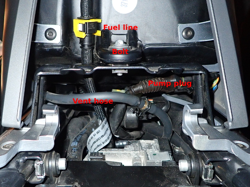
Move yellow clip on fuel line rearward & squeeze white "tabs"
to release line Picture "A"
Disconnect vent line (clip just down the line from tank) Picture
"A"
Disconnect electrical line under right side of tank Picture
"A"
Use hair dryer to heat tip over valve lines so they can be pulled apart Picture
"B"
Remove tank & set aside
 |
 |
|
A |
B |
|
| Thanks
to Grinn from ADV
for these pictures
|
||
Remove left coil (8mm socket 10mm wrench to hold nylock nut) Just loosen
as the mount has slots, & once loose, the coil can be lifted out of the
way
Picture #1
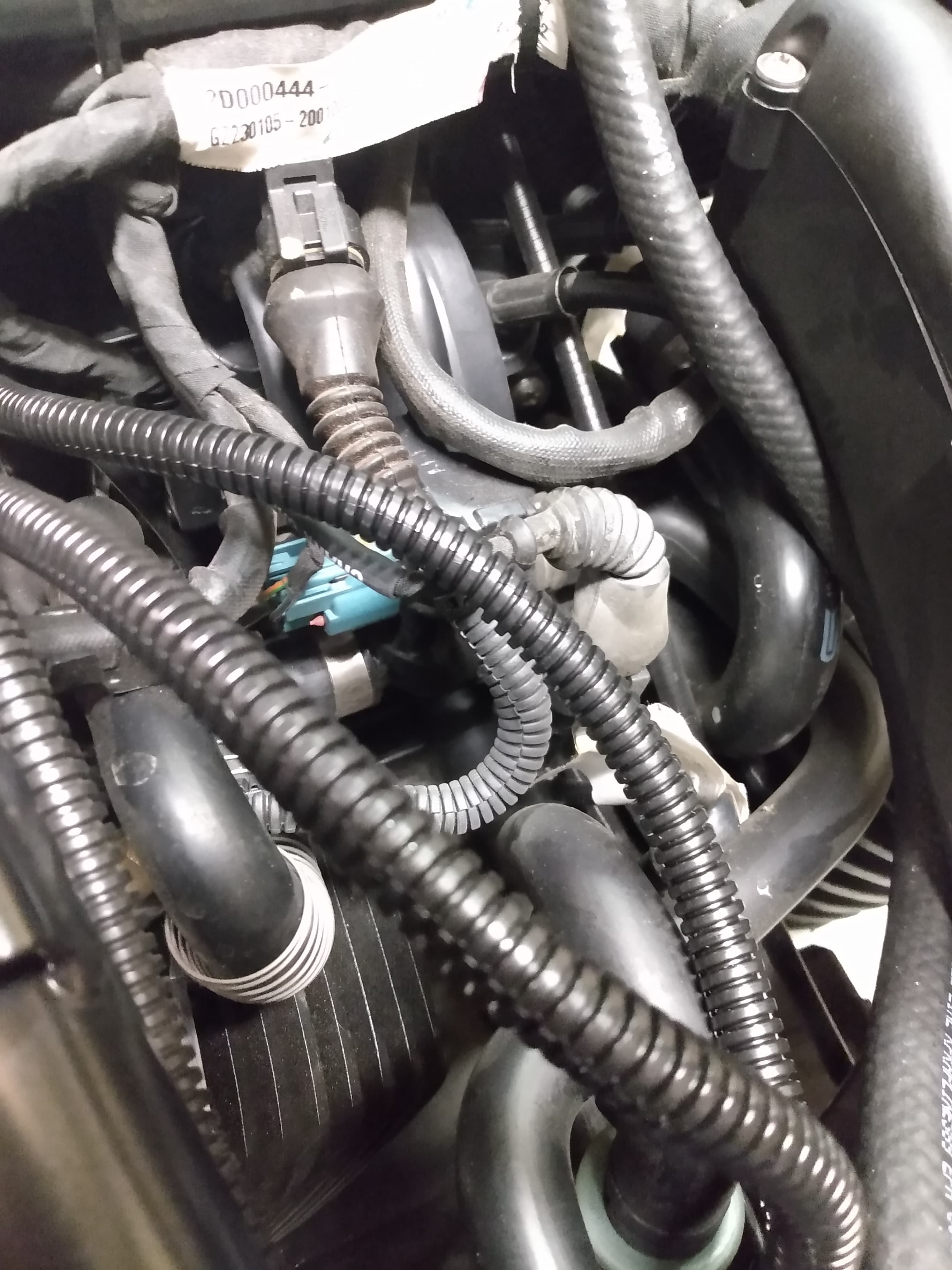
Remove both lines from black cannister Pictures
#2 &
#3
Toss tip over line in trash, as it's not needed again Picture
# 2
Pull black
cannister & toss in trash Pictures #3 &
#4 Note empty space in
Picture 4, this is where the Compressor will be
placed
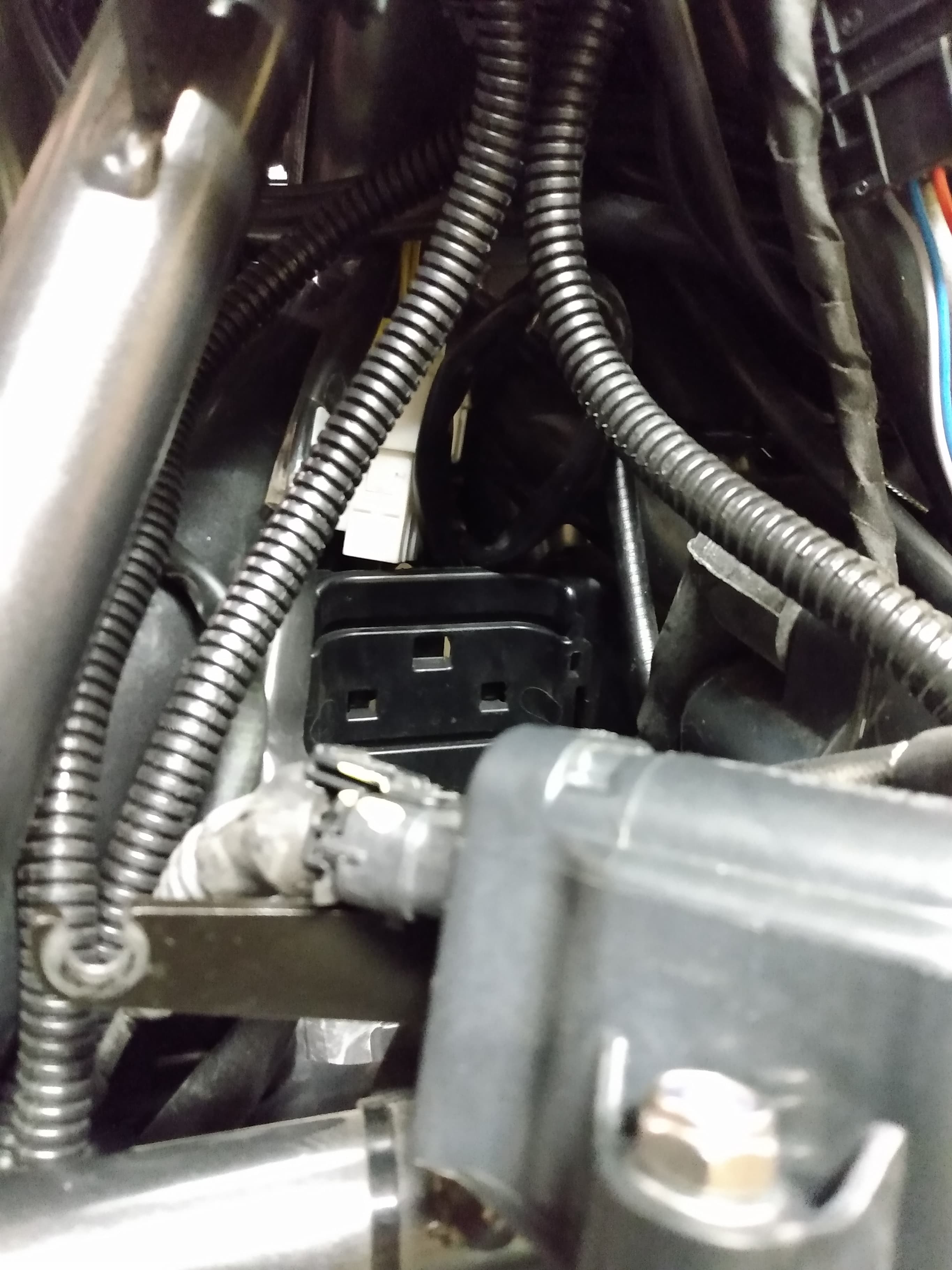
Plug other line but don't remove Pictures #5
&
#6 I covered the bolt/clamp
in tape, to help keep it quiet
10mm socket to remove stock horn
Disconnect wires from horn (toss horn in trash)
Pull OEM horn wires through frame & into empty cannister opening
they will be used when we
connect to the relay Picture
#7
 |
 |
|
Picture
1 |
Picture
2 |
|
 |
 |
|
Picture
3 |
Picture
4 |
|
 |
 |
|
Picture
5 |
Picture
6 |
|
 |
||
Picture
7
|
||
Stebel
Nautilus Compact Airhorn
|
||
.jpg) |
||
Before
Disassembly
|
||
.jpg) |
.jpg) |
|
Note
Air Channel |
This
"clamp" & mount will be trimmed |
|
I used a Stebel
Nautilus Compact Air Horn as I had a new one on hand
First I had to seperate it into 2 pieces, so the compressor would fit in the
empty space from the removed cannister.
Next I decided to "trim" the pieces & started by removing the
"clamp" that
attaches to the compressor body. (Pictures
#8, #9
& #10) Testing appears
to
show that the
trimmed horn
will fit in the same area above the compressor
Next I attached
the air channel, that I removed from the horn body, to the
compressor & secured it with a couple of zip ties (Picture
#11) & cut off the
original mount with a hacksaw. Then I used a glue gun for extra holding
power to
help secure the air channel (Pictures
#12 &
#13)
 |
 |
|
Picture
8 |
Picture
9 |
|
 |
 |
|
Picture
10 |
Picture
11 |
|
 |
 |
|
Picture
12 |
Picture
13 |
Next Step is attaching
airline to the compressor (id 1/4"/od 3/8). I used a
hair dryer to heat the tubing so it would slide over the connection on the
compressor Picture
# 14, I left this longer
than needed & will trim when
ready to inset into Horn body
Connect a red (+)
& black (-) wire to the compressor
& leave them longer
than necessary. This way the connection to the relay, will be in a location
where the relay can be replaced if it fails.
Connect a red (+) & black (-)
wire to the OEM horn leads & leave them longer
as mentioned above
I like using split loom
covering to protect wires Picture #15
& note they will
be ran closer to the frame & zip tied into place. Both of these looms,
run all
the way back to the battery tray where they will be connected to the Relay harness
The O/D of the airline
is too thick to slide into the hole in the horn body, so I
performed a little modification. I inserted a smaller diameter line, that I
had on hand,
inside the airline from the compressor Picture #16.
This was shoved up inside the
airline & I then cut the main airline, so that I could squeeze it into the
hole. It
wasn't going to stay in place without some help however. First I used some
"Crazy Glue" & then squeezing the line, where I had made the slit,
I twisted
& slid the airline into place. Once I was sure it had adhered properly,
I used a
hot glue gun & added some for extra security Picture #17
Once the glue had solidified,
I then inserted it above the compressor & secured
it in place with zip ties Picture # 18
 |
 |
|
Picture
14 |
Picture
15 |
|
 |
 |
|
Picture
16 |
Picture
17 |
|
 |
||
Picture
18
|
||
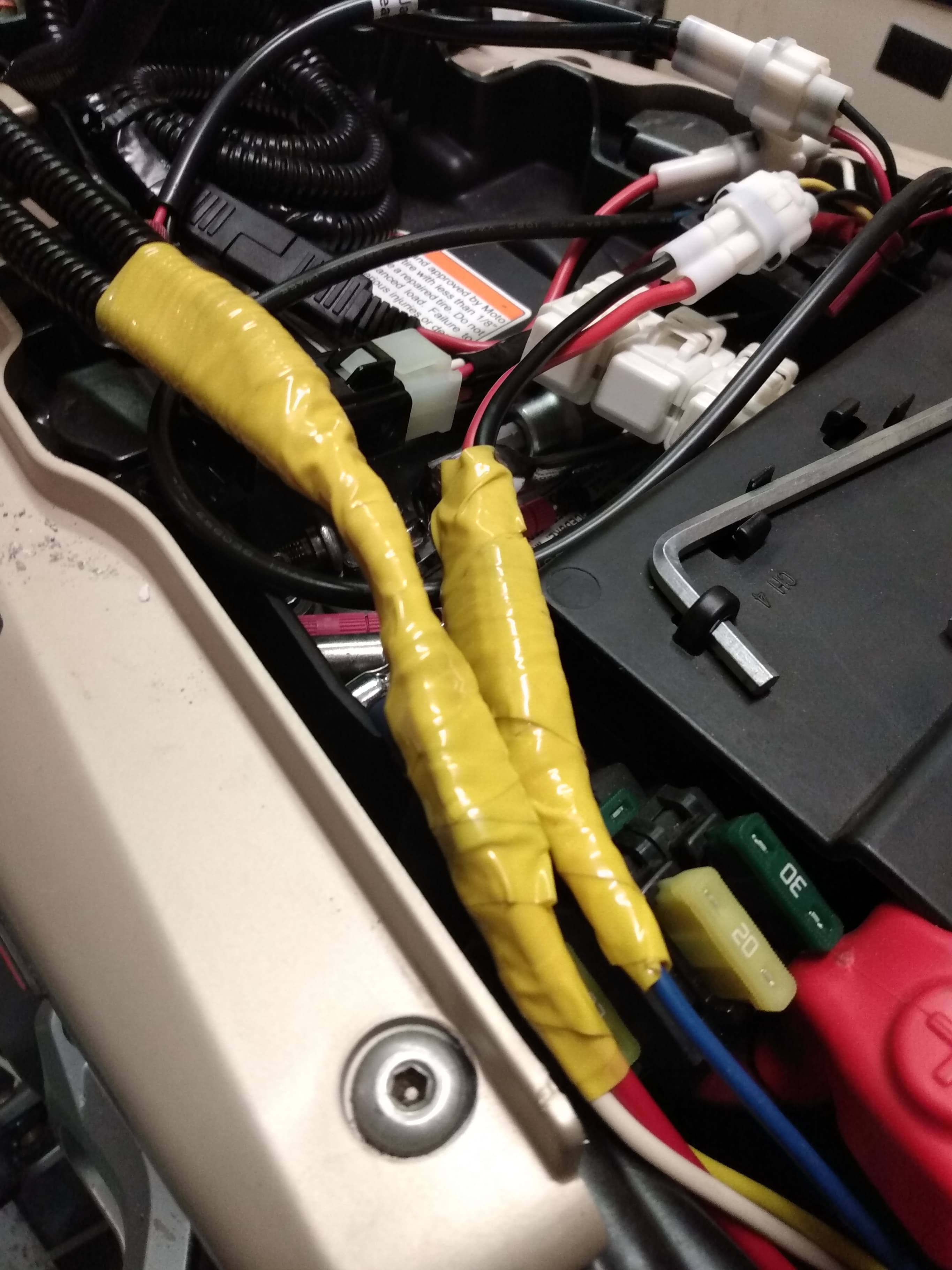
Final step
is connecting the OEM & compressor wires to the Relay
& the Relay to a switched & Fused power source
Picture # 19 (Disregard wire colours if not using a relay pigtail)
87 is Yellow positive from compressor
85 is Red OEM Horn Power
86 is white OEM Horn Ground
30 is blue switched & fused power
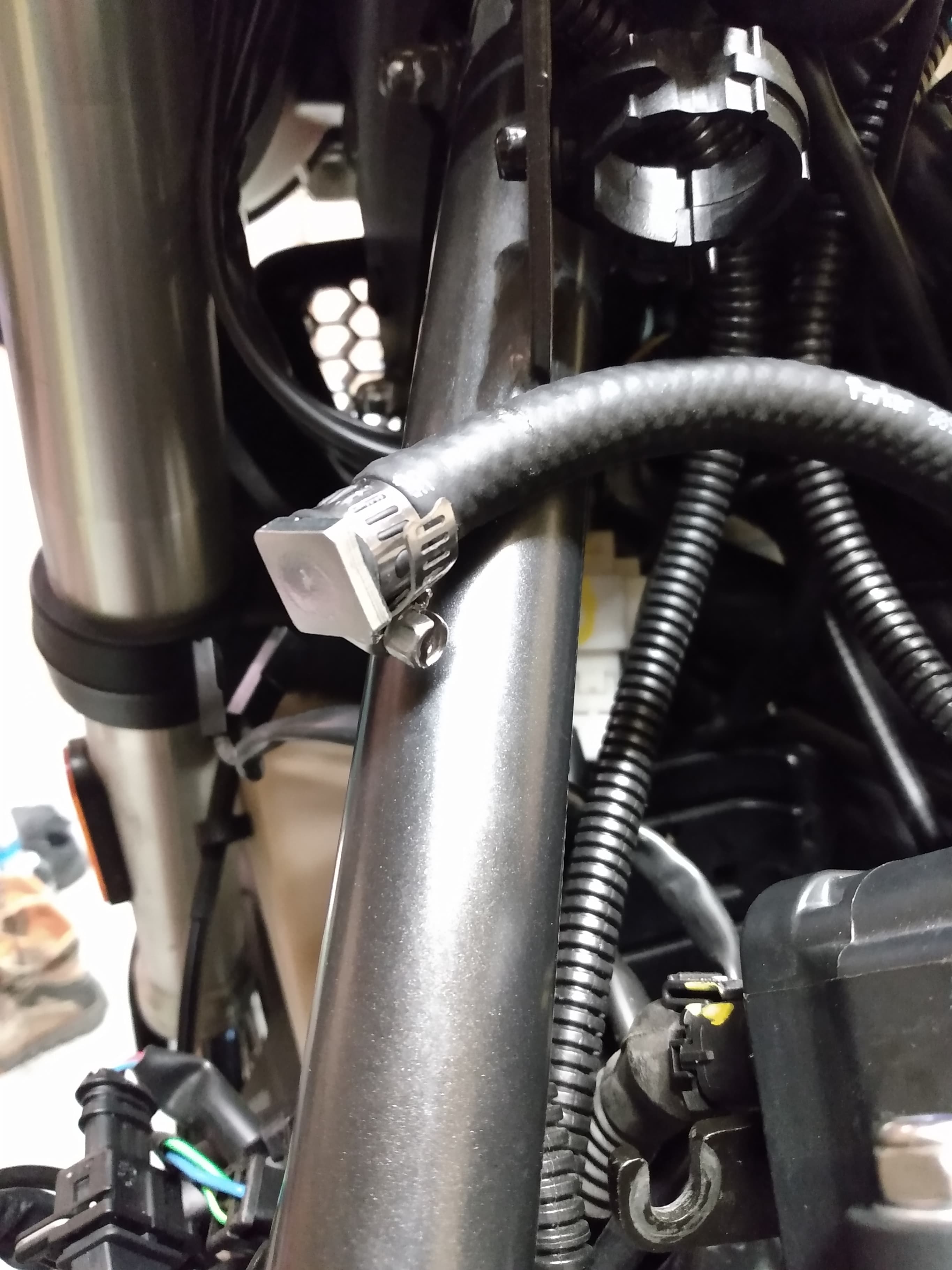
I took the
ground wire from the Air Horn Cimpressor, stripped a long
strip of insulation off & wrapped it around an engine mount bolt on the
left side of the bike. I loosened the bolt enough to wrap the bare wire
behind it & then tightened it back up Picture
# 20 ( I may change this
with a "proper" spade connector, at some point in the future)
Pictures # 21 &
# 22 show the wire loom(s) secured to the frame
with a zip tie & tape around my crimp connections, for extra protection
 |
 |
|
Picture
19 |
Picture
20 |
|
 |
 |
|
Picture
21 |
Picture
22 |
![]()
There
is a lot of useful information on this site, but errors are possible
All Images/external links open in New Tab
Helpful
answers are $1.00 each ![]() dumb looks are still FREE
dumb looks are still FREE ![]()
These Tips come from many people,
on the various
motorcycle forums I frequent.
![]()
If You Attempt Modifications & Ruin Your Motorcycle
It Is Your Problem.
If You Are Not Mechanically Inclined,
Get Help From Someone Who Is
I Am Not Responsible For Use/Misuse Of
These Tips & Tricks
Use @ Your Discretion
![]()

 |
©
2002------->
Alberta
Adventure Rider |
|